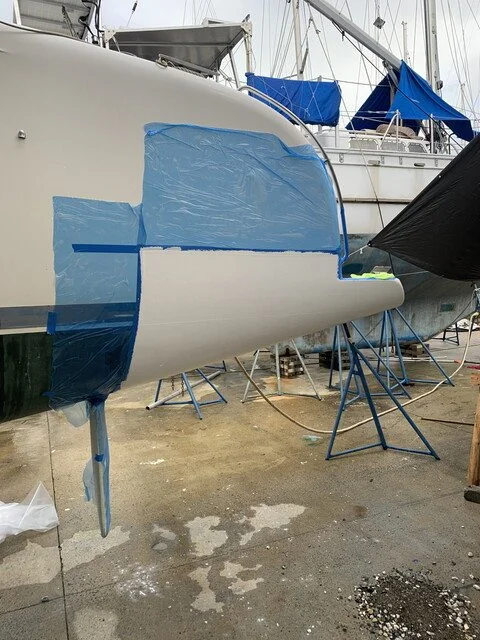
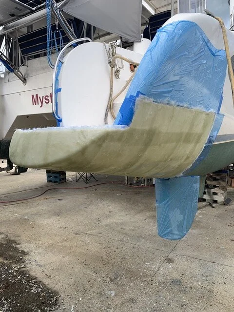
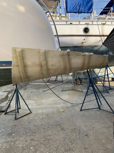
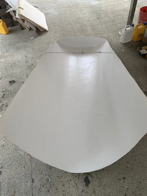
Stern Extensions
Extended sterns
We’ve been back in the water for about four months since our haulout at RAM Marina in Guatemala. One of the big projects Mark took on was a stern extension for our Dolphin 460. It was déja vu all over again ~ since we did this exact same thing with our Manta 40 in the same place in 2014!
Our experience with the Dolphin 460 extensions has been excellent so far. To our pleasant surprise, we are about 0.5kt faster under mid-range rpms and a full knot faster under full rpm. The main reason for this is that our sterns are not squatting underway. Under sail, we appear to empirically be at least 0.5 kt faster or more.
This reflects a fairly equivalent comparison of the boat with a smooth bottom, previously with coppercoat (which is a smoothed epoxy surface) and currently with our new coat of Ameron ABC3 ablative pain.
The Process:
Think for several years about it
Design lines and come up with a plan
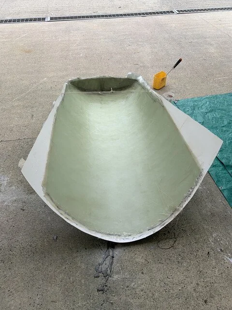
Make female mold from existing stern shape
Prepare mold for layup and make stern
Cut to fit and glass in place
Glass in bulkhead
Lay up top step with nonskid pattern and install
Glass to shape, fill & fair, fill and fair some more
Repeat other side using same mold (symmetrical)
Epoxy barrier coat & bottom paint
One of the questions most commonly asked is “Why the stern extensions?”. A number of factors came into play for us, and knowing that the extensions themselves are relatively straightforward and we were hauling anyway, we decided to go for it.
A few factors that led us down this path were:
We have heavier 55hp Volvo engines in the sterns (previous owner installed in lieu of standard 40hp)
We had just eliminated ~700lbs of weight in the port bow by removing a 8kw Kohler generator
Our Carib C12 RIB dinghy is a bit overly built and heavy on the davits
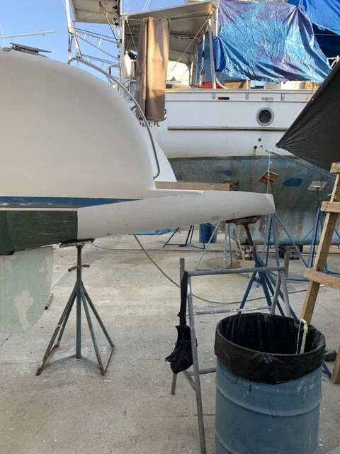
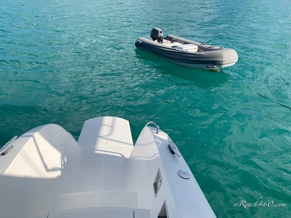
The high cheeks on on the Dolphin 460 sterns gave a fairly small boarding surface from the dock or dinghy
Extended sterns offer a larger platform for boarding and diving with gear
Longer waterline adds to sailing performance
Stern buoyancy offers less drag under power
Buoyancy needed for additional solar panels aft
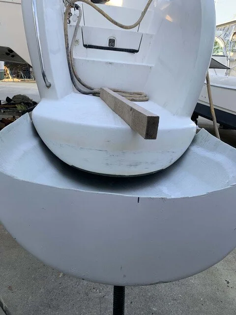
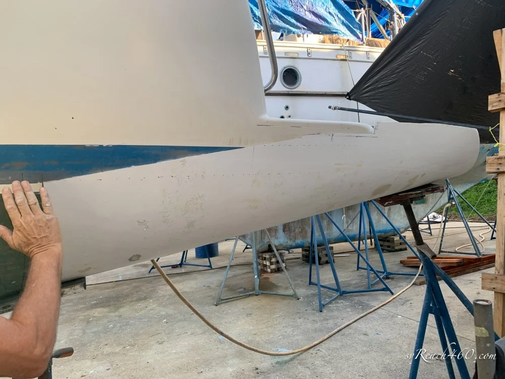
For reference, Here are some “before photos” of the sterns.
I am usually the documenter and photographer for this website, translating Mark’s research, rationale and hard work into a photo story.
For the rest of this blog, I am going to post Mark’s description of the process in his words, which he shared with the Dolphin owners group. As always, I’ll be able to offer the photos to show the whole process from start to finish.
Design & Rationale:
On our current haulout, we decided to make a Dolphin 475 by adding 20" to the sterns. The reason is to better balance the boat and to provide a bit more useful landing area. Dolphin really should have shortened the side cheeks a bit more than they did to make an easier dinghy landing area, but the main reason for the addition is that after adding 800w of solar over the davits, putting on a large RIB, and removing the genset from the bow, the sterns were really dragging.
Just pulling out the stern following the hull rocker lines wouldn't help much because there wouldn't be much buoyancy added, and it would end up with a small pinched transom that would be ugly and not practical. So the challenge was to drop/flatten the stern rocker to increase the overall hull volume and end up with the same transom profile.
I'm going to use this thread to document the build. First, the thinking part:
The attached picture is a mockup using strings and a foam transom that I used to make different stern profiles so I could get some measurement data for volume calculations and visually see how different rocker and length configurations interacted and effected things. The orange string is the centerline bottom of the hull.
Simulating lines
After considering a lot of different configurations, we decided that dropping the rocker 3" and adding 20" to the length would give a nominal extra 300lbs of buoyancy in the sterns. This is "nominal" because it is based purely on added volume, and I can't get a good calculation for the effect of the additional lever arm that would be added with the length. This could be up to 100-150lbs more buoyancy, depending on where one chooses to place the fulcrum in the calculation. Given the non-linear volume change that occurs in the stern, the estimated positioning of the fulcrum in the calculations go too complicated for me, so it will just have to remain "it is what it is, and we will see when it is back in the water".
The rocker could be dropped 4", and the length increased to 24-30", but at that point, a bustle is being introduced in the stern, which describes a situation when there is a "hinge" point where the stern flattens out compared to the rest of the hull before it. Too much of a bustle is just increased drag, which negates removing the drag from the originally submerged stern by making it longer. So approximately 4" removed from the rocker, and 24" added to the stern is pretty much the limit of what should be done. We decided to be a bit more conservative. After all, it is easier to add that in later than to take it back out!
My goal was to bring each stern build in at 50lbs, and (spoiler alert) I hit that mark. So the net increase in buoyancy, minus any additional lever arm, will be 200lbs.
Making the Mold:
Once all the calculations were made, and we were visually happy, it is time to make a mold. Only one mold is needed because the hulls are symmetrical.
Right? Well, turns out they are not. Dolphin did not get the original mold symmetrical, and the port hull is slightly shorter in length and slightly more rocker, and slightly shorter in height. Around 1/2-3/4" depending on which dimension. I made a mold from the starboard hull and didn't realize the port hull had different dimensions until after I had built the port stern from the mold and was fitting it.
Not too big of a problem, because those dimensions are relatively easy to compensate for once you know they exist. And if you don't compensate for them, then you are none the wiser because you didn't know it came that way from the factory in the first place.
Anyway, on to making a mold.
The mold was made from just aft of the rudder post. The hull above was masked off, the bottom waxed with mold release wax, and then PVA mold release was added on top. Our bottom antifoul was Coppercoat (at the time), which didn't require removing to make the mold. If it was antifouling paint (which is what it will be in the future), then that would need to be removed first.
After masking and waxing, a couple of coats of gelcoat was put on, then two layers of chopped strand mat glass after the gelcoat had cured. When the fiberglass had cured, stringers were added to maintain the shape of the mold when it was removed.
Then the mold was popped off and ready to make new sterns in.
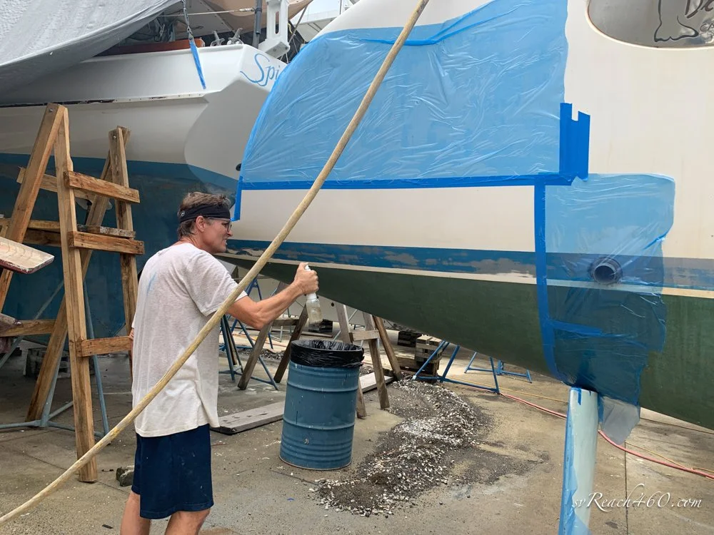
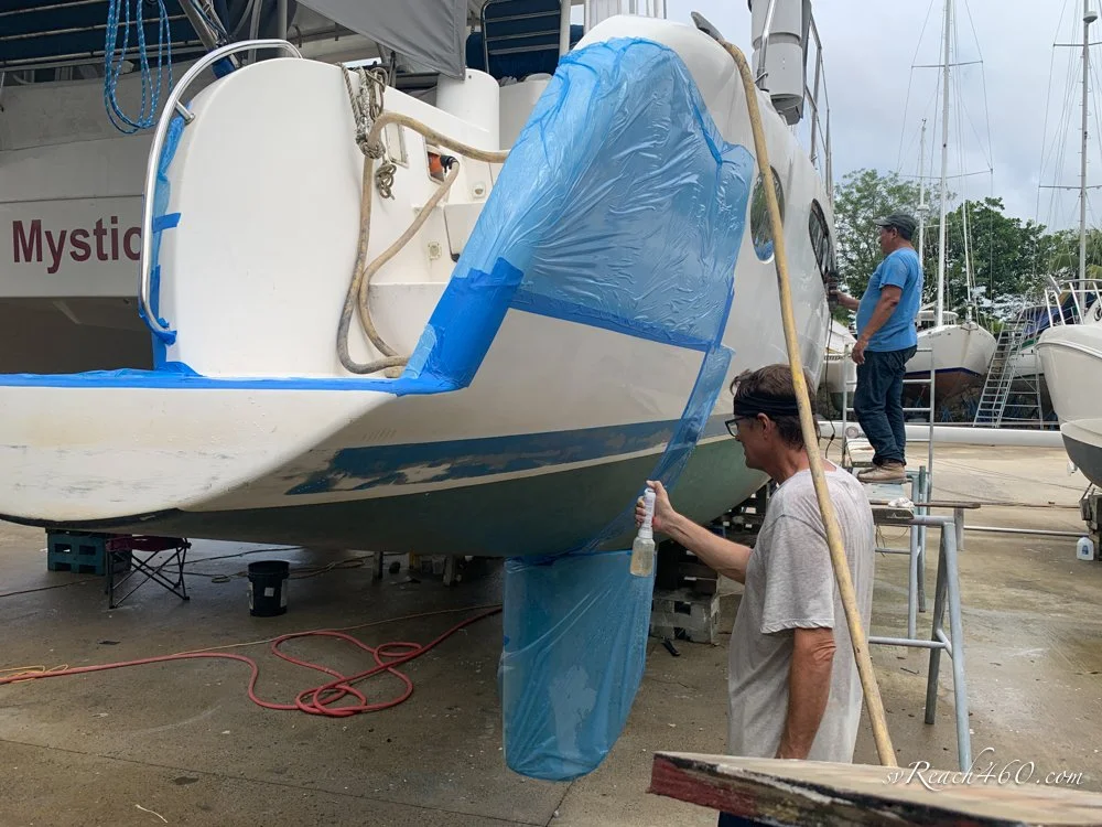

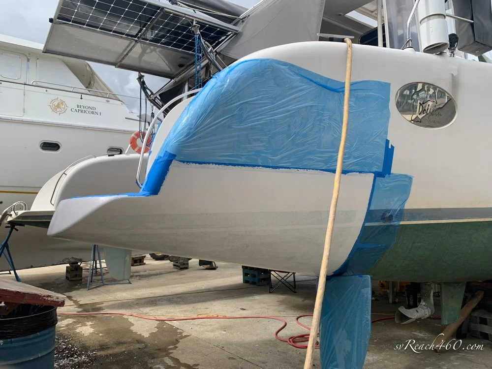


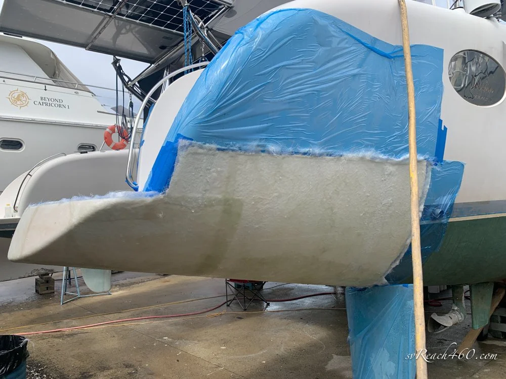


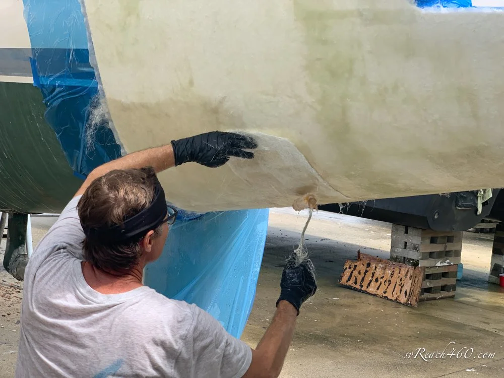
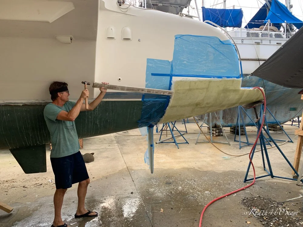

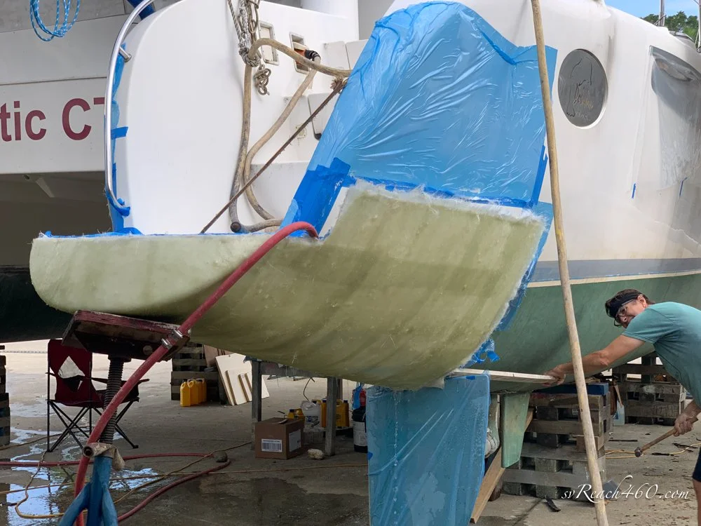
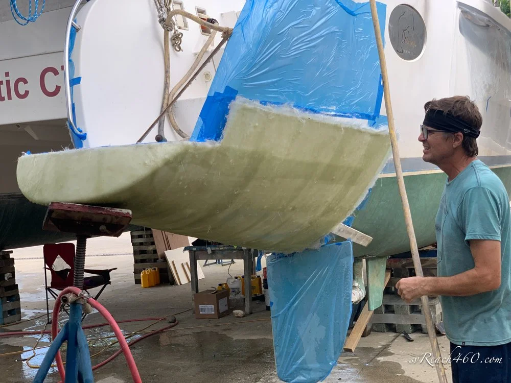
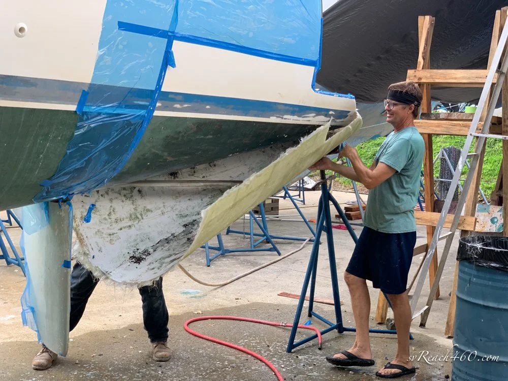
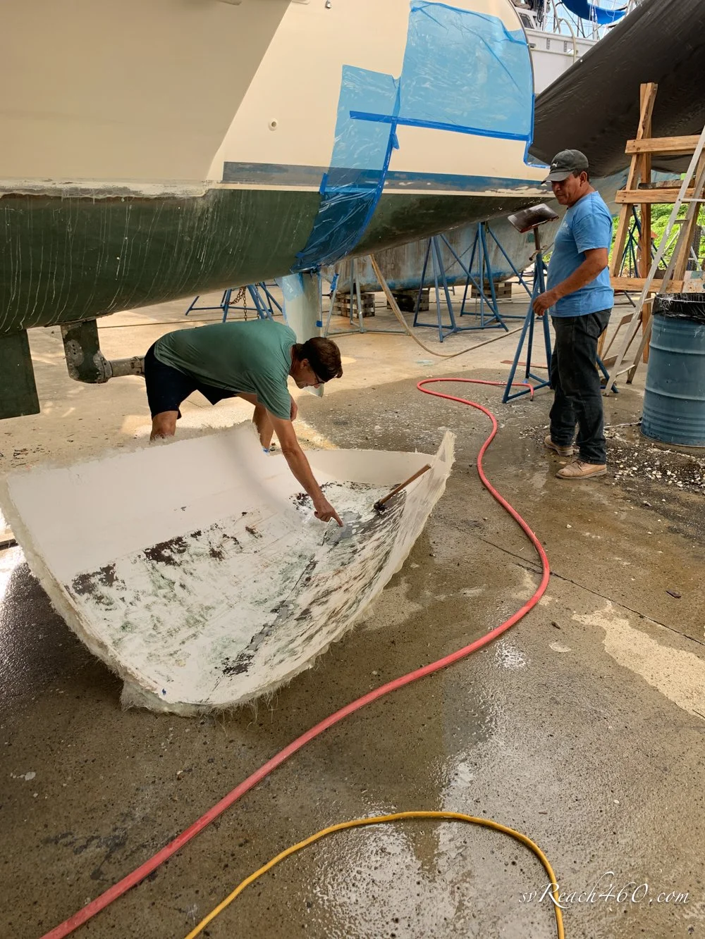


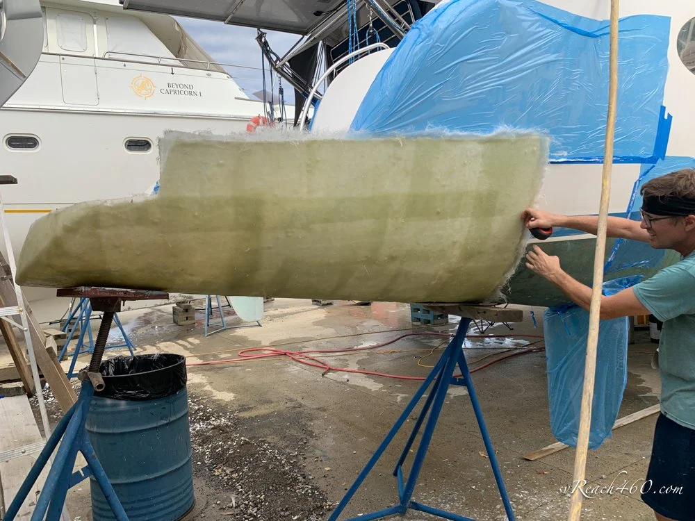






The mold was made larger than necessary, but I wanted to make sure I had sufficient area to work with. It is easier to cut down the stern builds to fit than to add to them after they have been made.
Making the Sterns:
On to making new sterns in the mold.
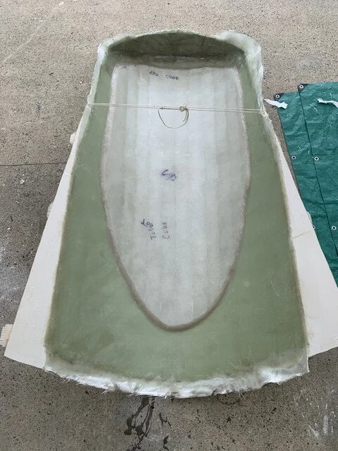
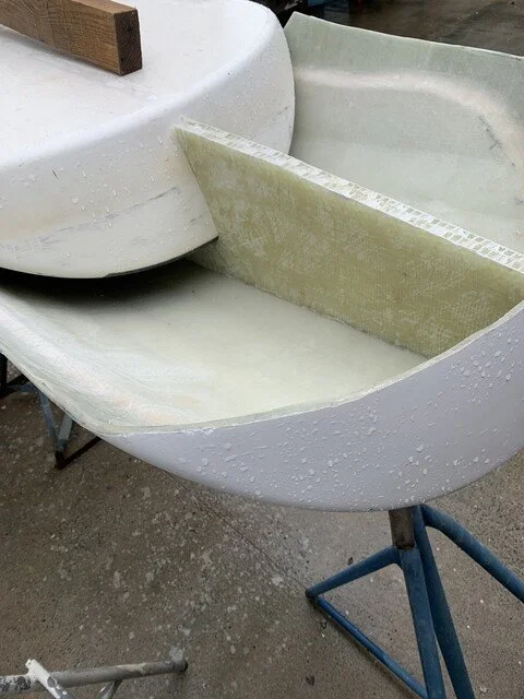
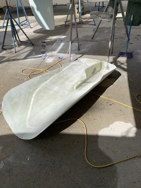
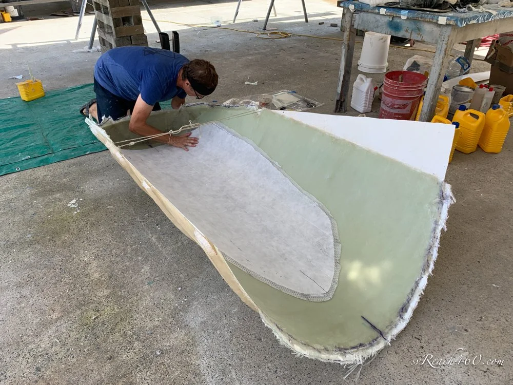
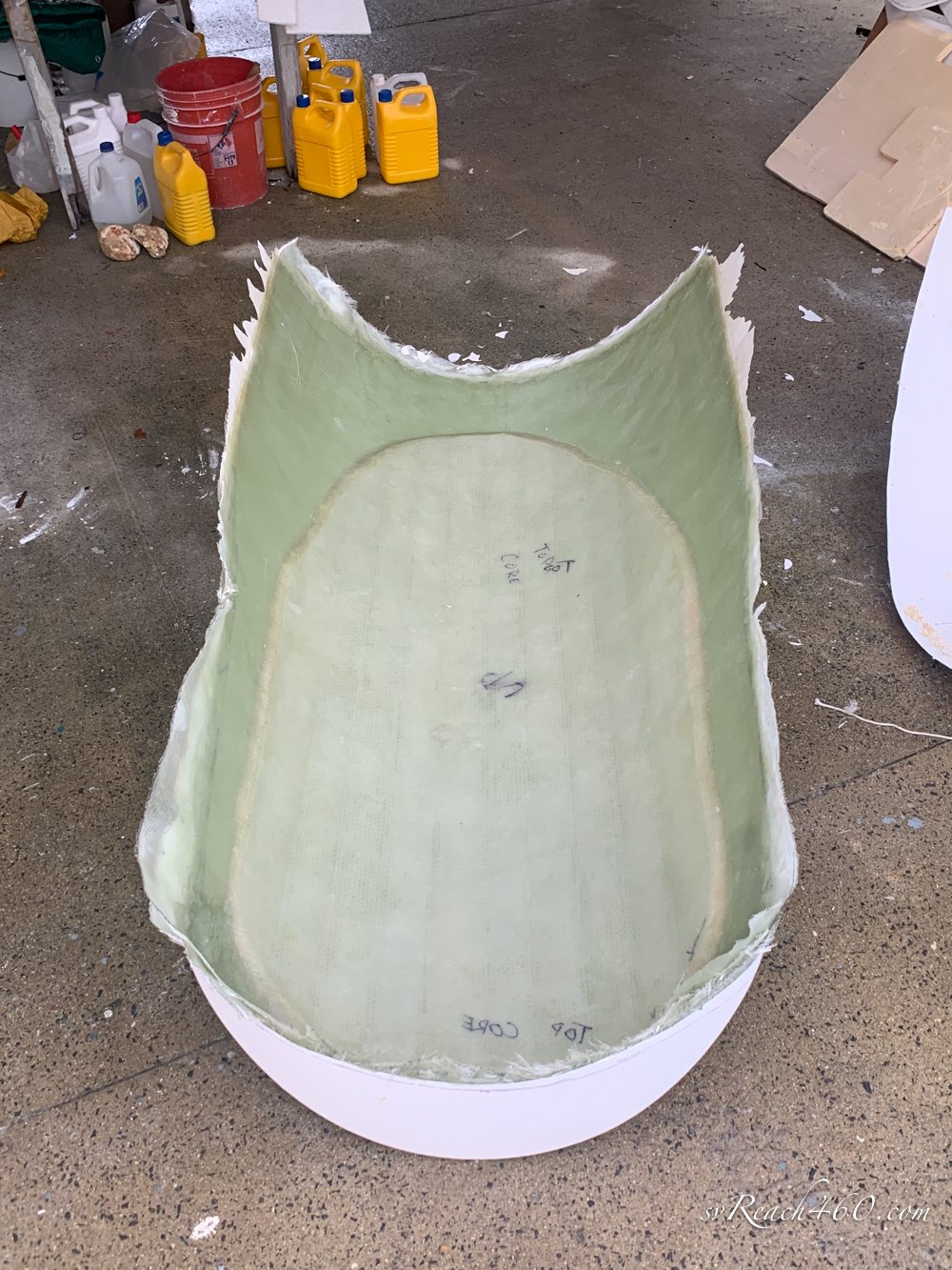
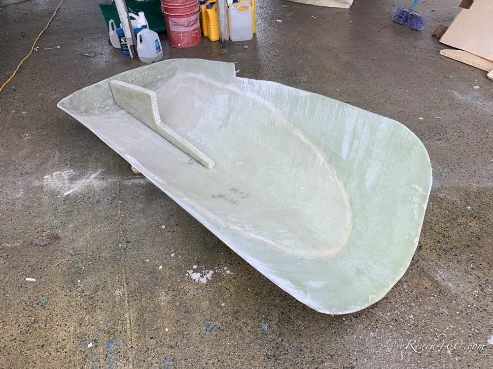
The layup schedule for the new sterns was decided at 3 layers of 1200g/m2 triaxial stitched fabric followed by a 12mm polypropylene honeycomb core, with another layer of the same triax glass on top of that. This gives a 5mm bottom skin and an overall thickness of ~19mm. No calculations were done to decide on this - it just seemed "right".
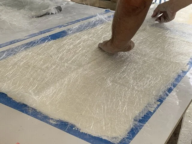
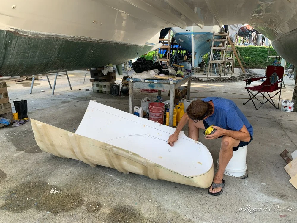
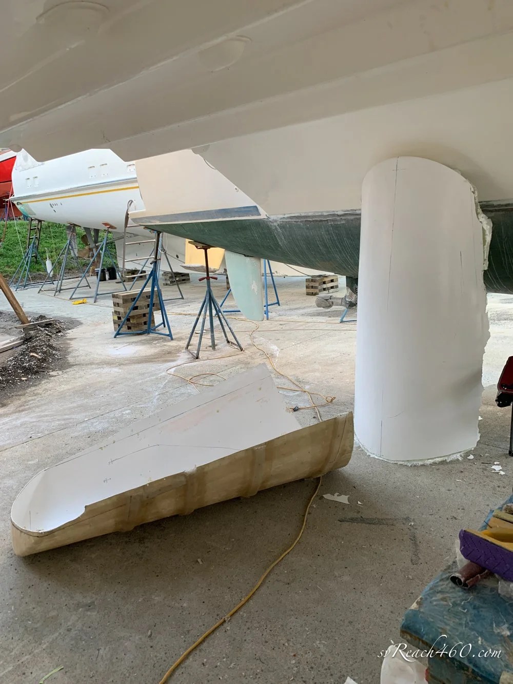
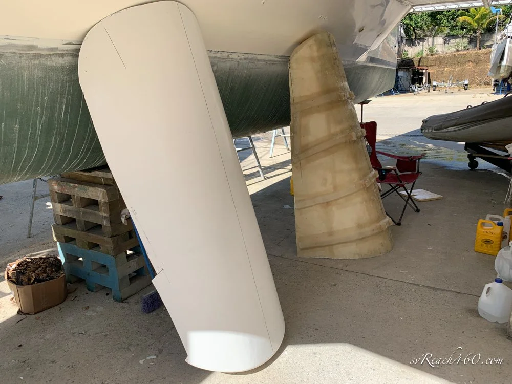
Following what will become a very familiar pattern, the mold was waxed, PVA added, then gelcoat. When the gelcoat set, 3 layers of glass was layed up, the core was glued in, and another layer of glass put over it.
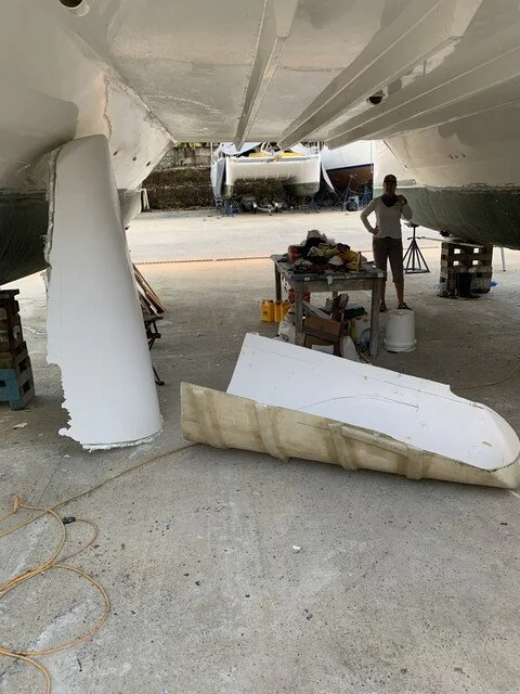
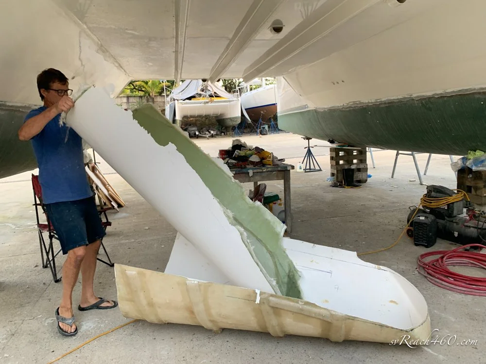
When all of that had cured, the stern was popped out of the mold ready to be trimmed to fit and installed.


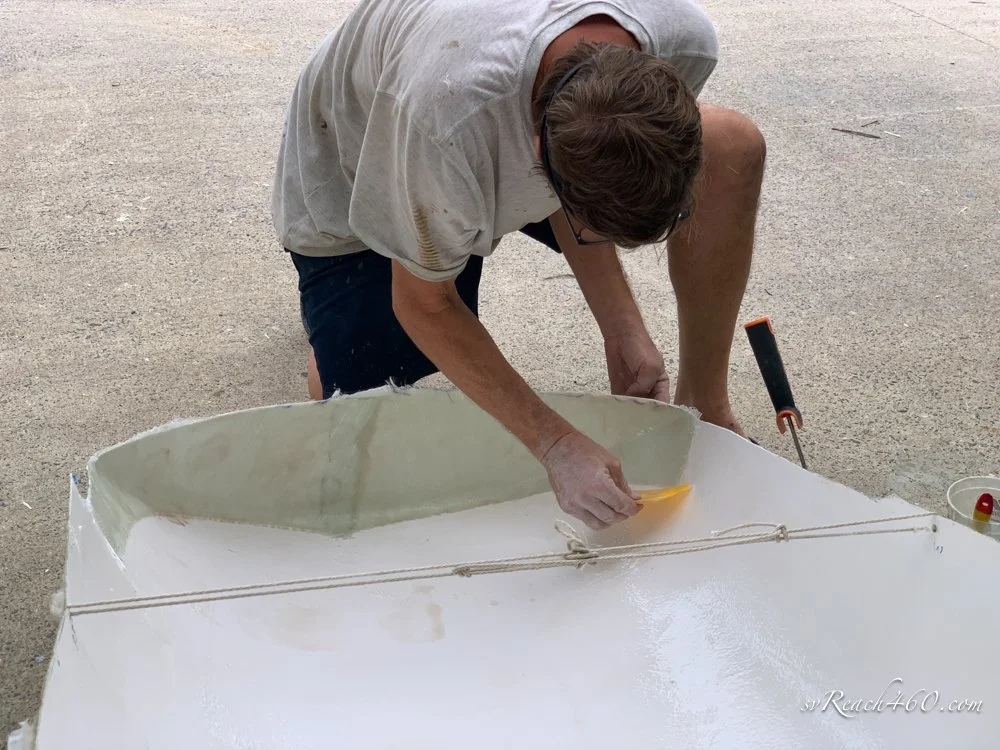


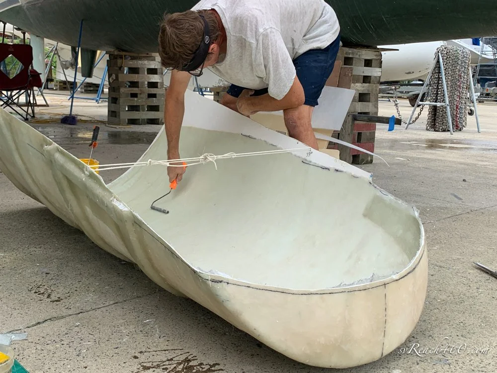
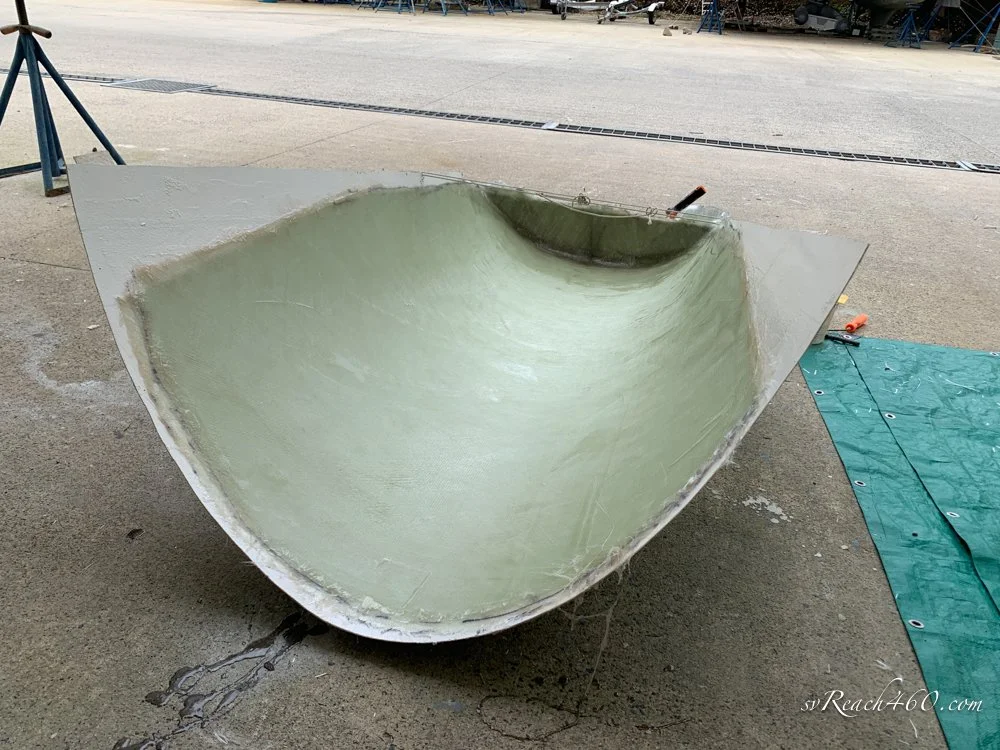


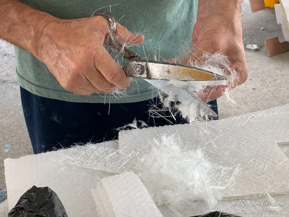

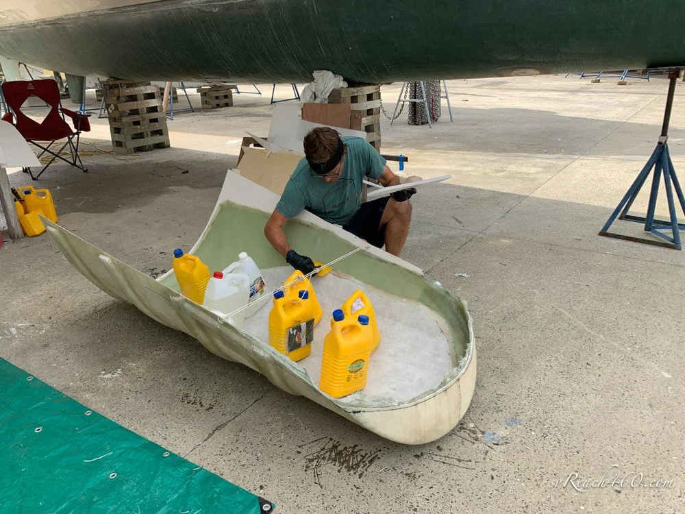
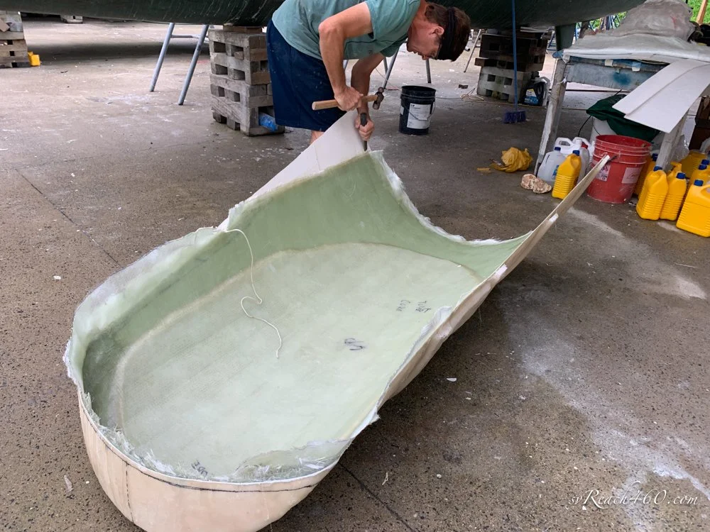

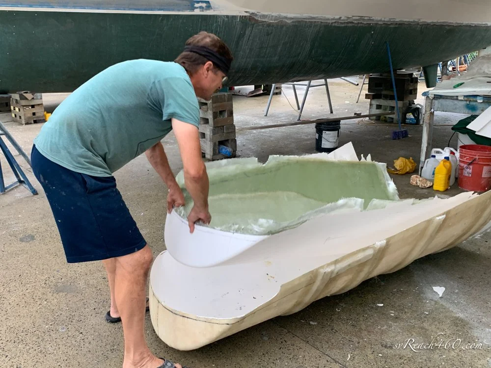


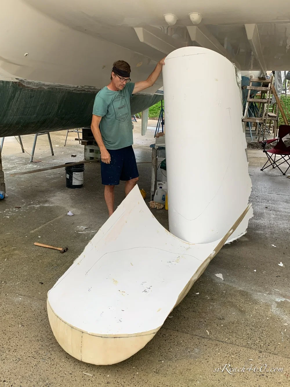
Removing stern from the mold
This was repeated for a second stern ~ Port side layup:










Install & Glass Sterns:
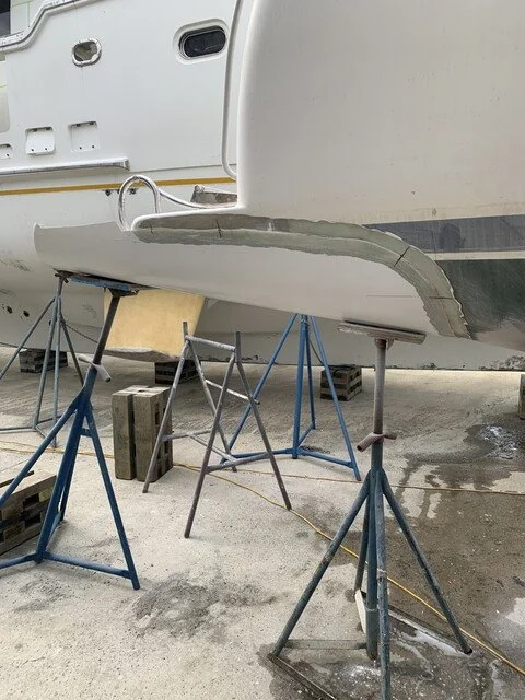
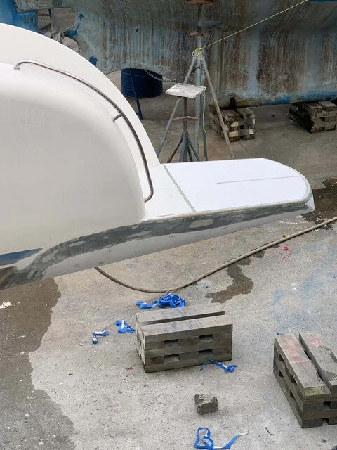
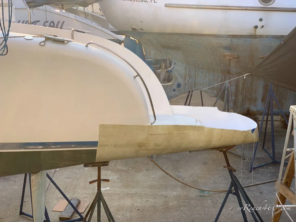
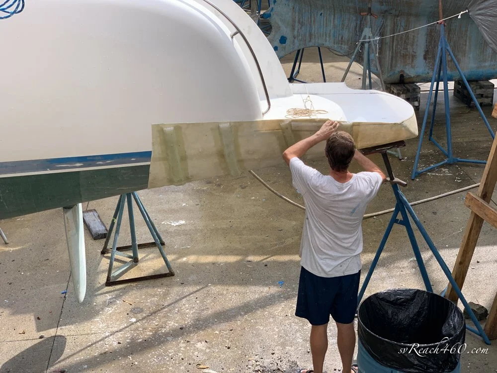
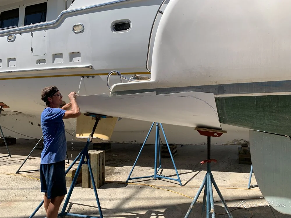
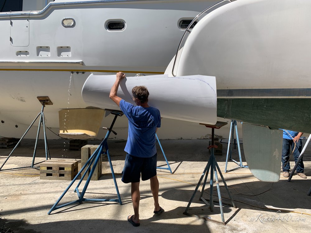
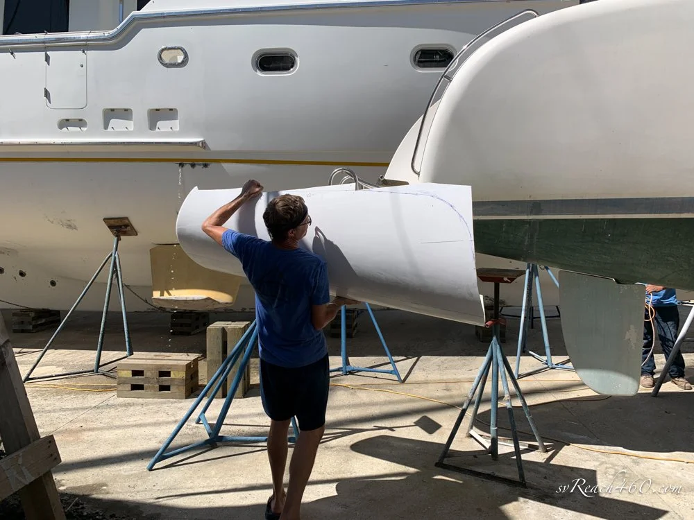
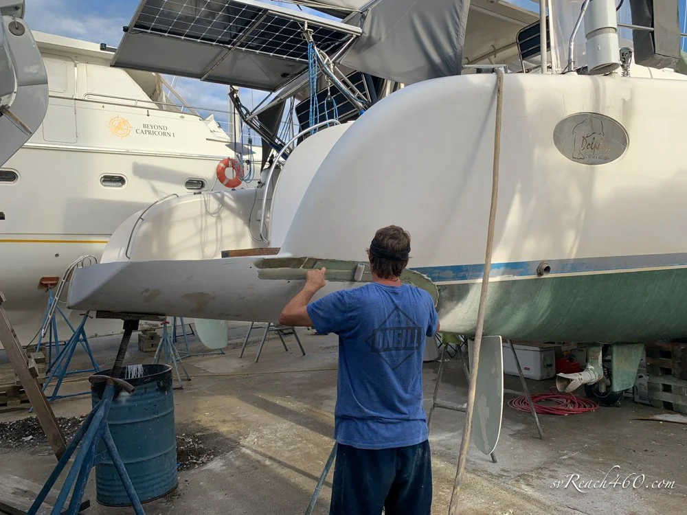
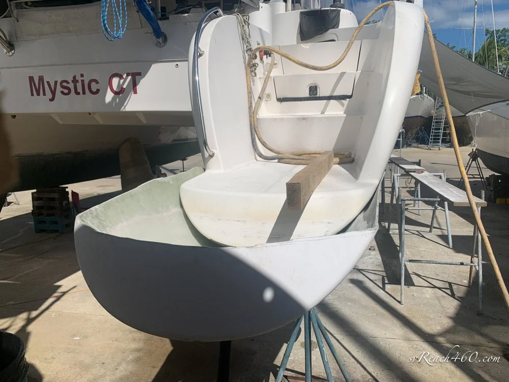
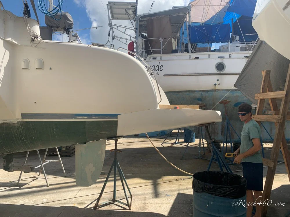
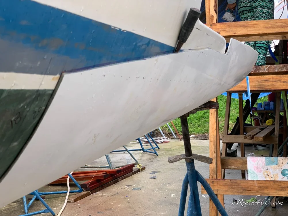
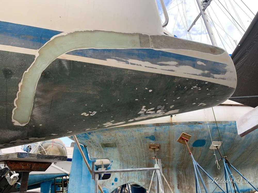
Now that the stern hulls are made, it is time to install them. They are held up and adjusted using jack stands to the wanted angle and length, and then trimmed to the size needed. Grind a bevel around the seam area on the boat and stern, and then glass it on.
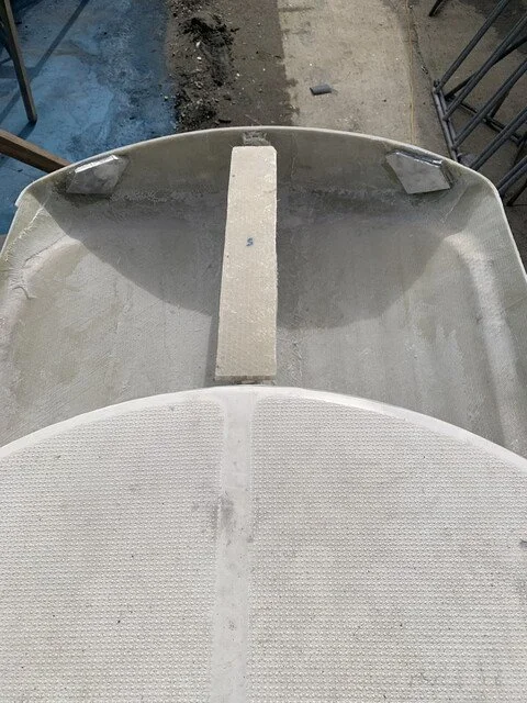
A couple of details: a bulkhead is glassed into the new stern that will also be glassed to the hull. This provides additional support under the hull that continues the bulkhead already there, as well as provide a support for the new deck top to come. In one picture you can see the additional volume between the new and old hull.







Installing the ladder:
Our ladder has always leaked from the bolts holding it onto the step, but I have been unable to reach them to take it off and reseal. I'm tall, skinny, and have long monkey arms, but could not get all the way back to them. I finally figured out how to reach them...
The ladder will be reinstalled differently.
Improved ladder access ~ Lol
Making the tops:
Onto making the tops.
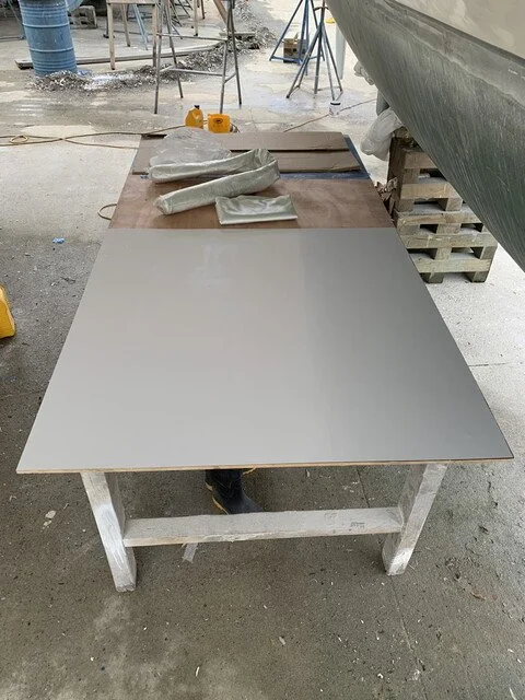
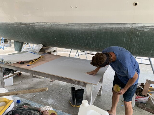
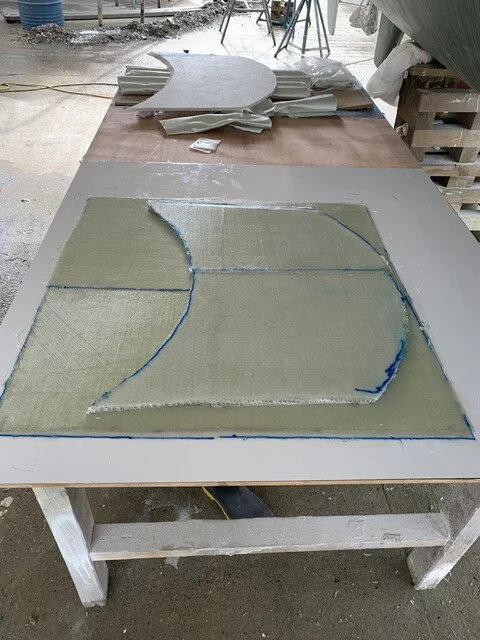
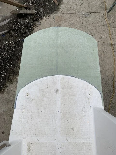
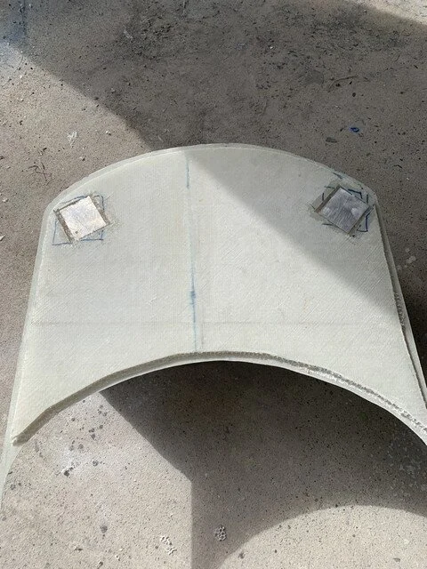
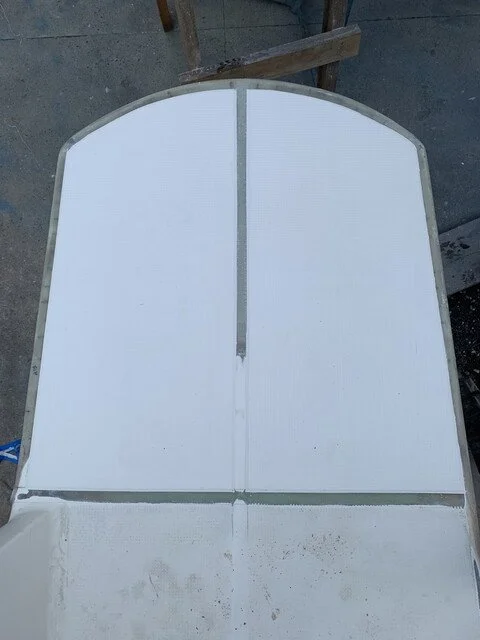
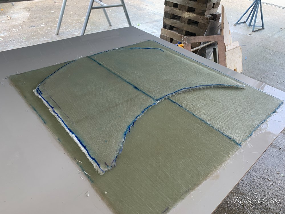
These are easy, as they are just flat tops extending from the existing ones. I made a layup table by gluing formica onto a piece of plywood. This is waxed and treated with PVA like the mold, then gelcoat is added, after which the same layup as the sterns - 3 layers of triaxial, a 12mm core, then another layer of triax on top.
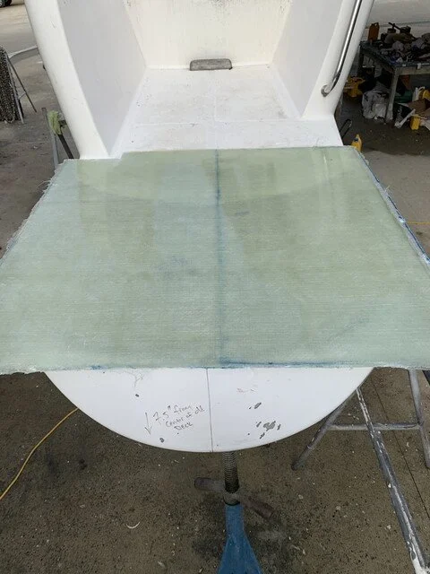
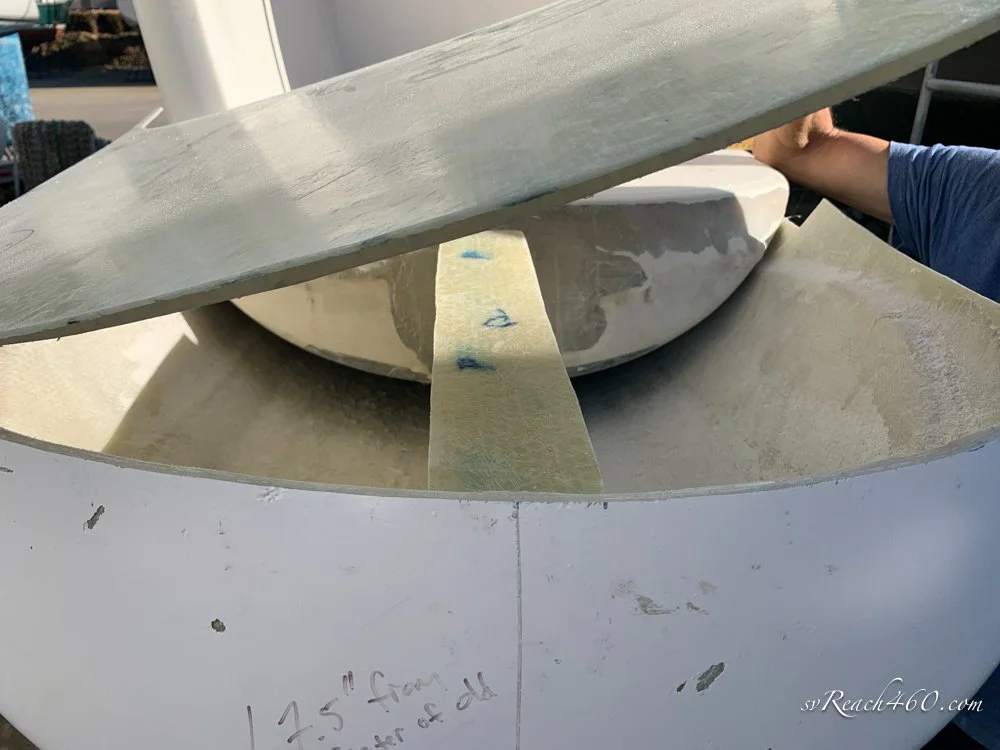
When cured, it is lifted off the table, put on the stern and trimmed to size.
A couple of details: a horizontal piece is glassed onto the vertical stern bulkhead. This will provide extra surface area for gluing the top down. On the ladder stern, 1/2" aluminum plates are embedded and glassed into the top and transom. These will be drilled and tapped, and the ladder bolted on from the outside, so there will be no need to ever have to reach nuts back there again.


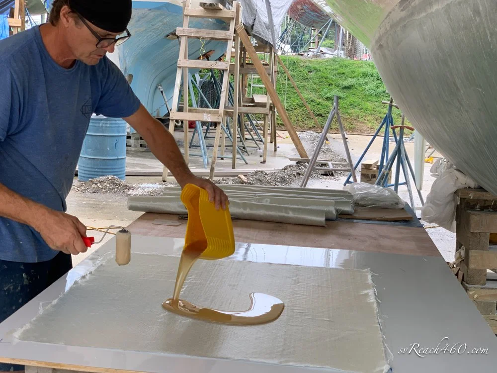


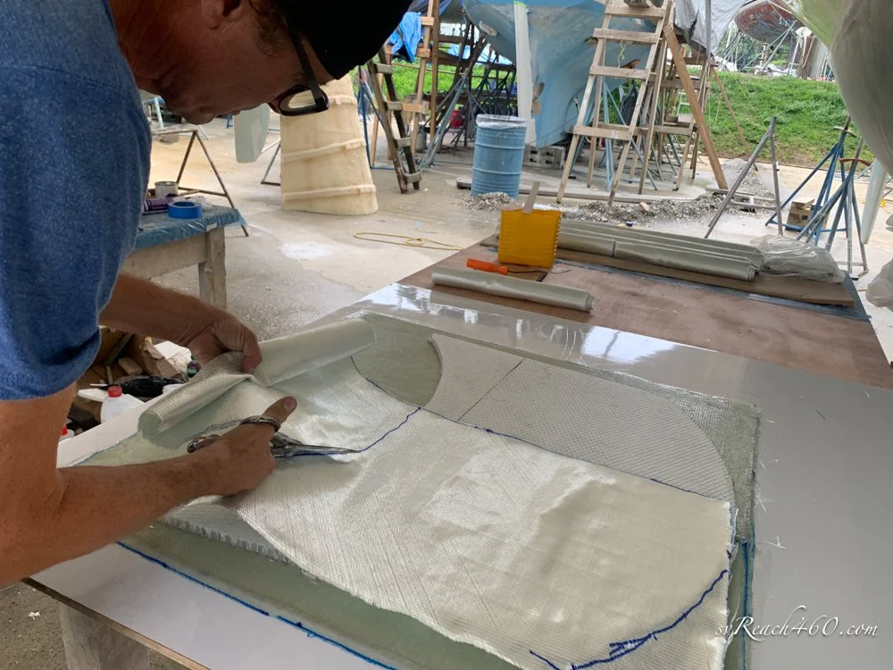





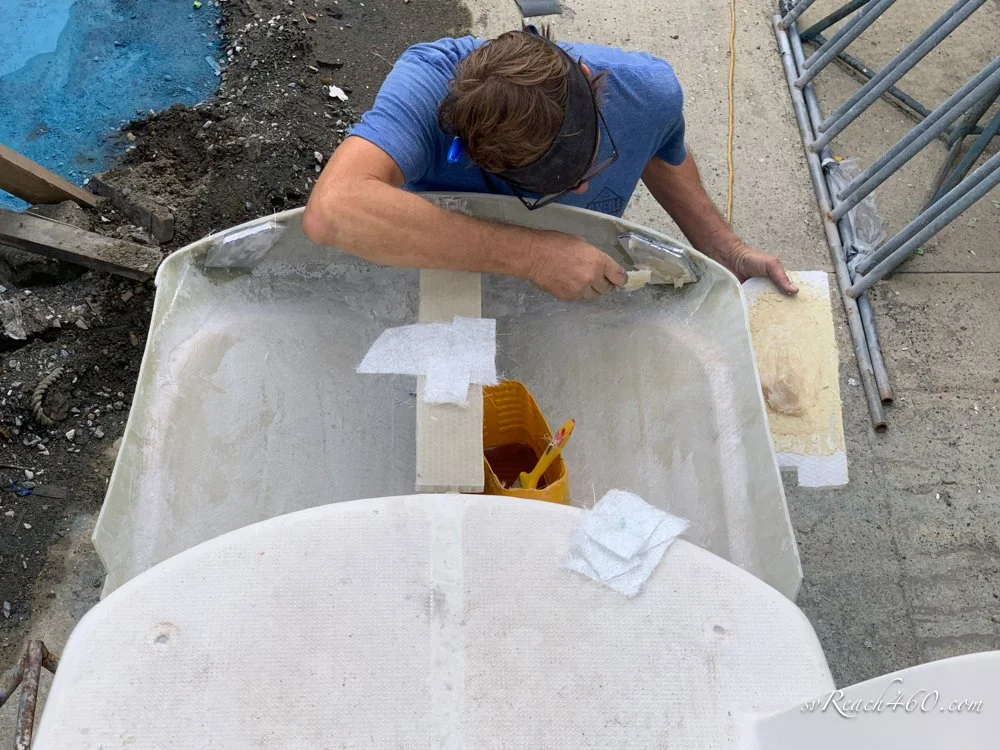

Making the non-skid:
A bevel is ground around the top like was done with the hull, and the top glassed on, as well as glued down onto the bulkhead platform.
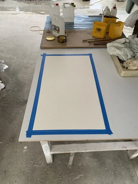
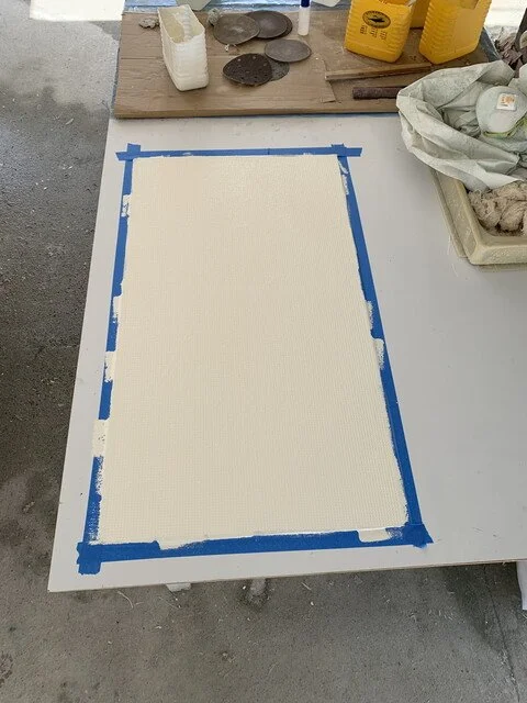
Time to make new nonskid for them. For this, I used the cockpit locker lid to make a mold because it is the largest piece of continuous nonskid on the boat. Just like in making the stern mold, it is waxed and PVA'd, gelcoat is added, then two layers of CSM glass. Pull it off and you have a mold for making new nonskid.
Then you do the reverse with the mold - wax and PVA, gelcoat, then CSM glass. The difference this time is that the gelcoat is now color matched with the rest of the boat so the nonskid will match.
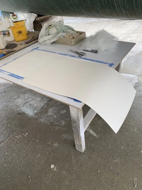
Here, you do a trick few know about. You don't really want this nonskid to be very thick because it will be taller than the existing, so you don't want a thick layer of glass on the back. Typical 3/4oz CSM is made by blowing layers of chopped strand on top of each other. If you are careful, you can separate these layers and end up with a very thin layer of CSM that is just enough to support the gelcoat and provide a gluing surface.
When taken off the mold, the nonskid piece is flexible like vinyl floor tiling squares and is easy to cut to shape with scissors.
Zip it up:
Homestretch.
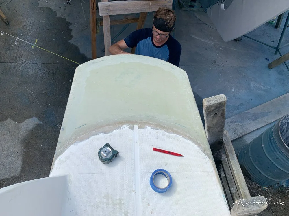
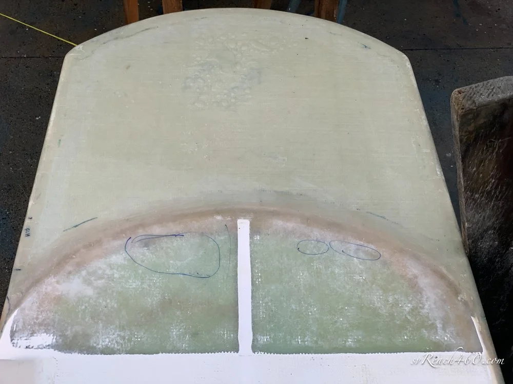
Trim the nonskid to fit the top. I added smooth channels down the middle and across the top to mimic the existing ones and allow water to drain easier. Glue it down to the tops, treat the edges with a bit of thickened gel coat to smooth the transition, and the sterns are finished.
I skipped the step of fairing out the glass seams all around. Just some fairing compound and sanding to make them smooth and transition seamlessly.
Grind & Shape:
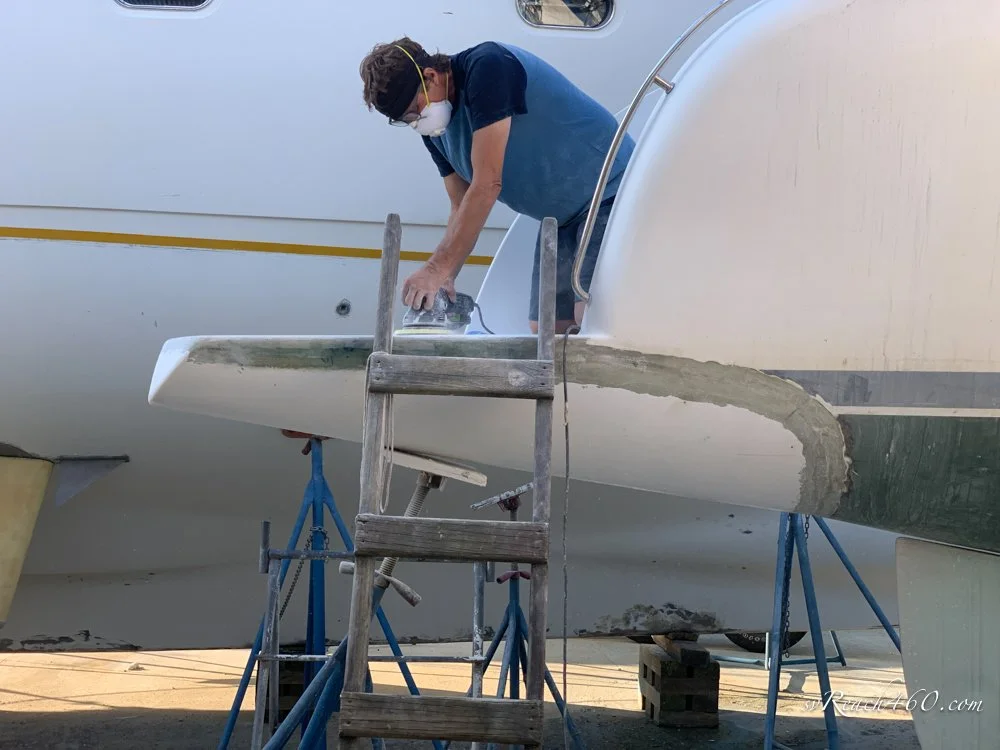
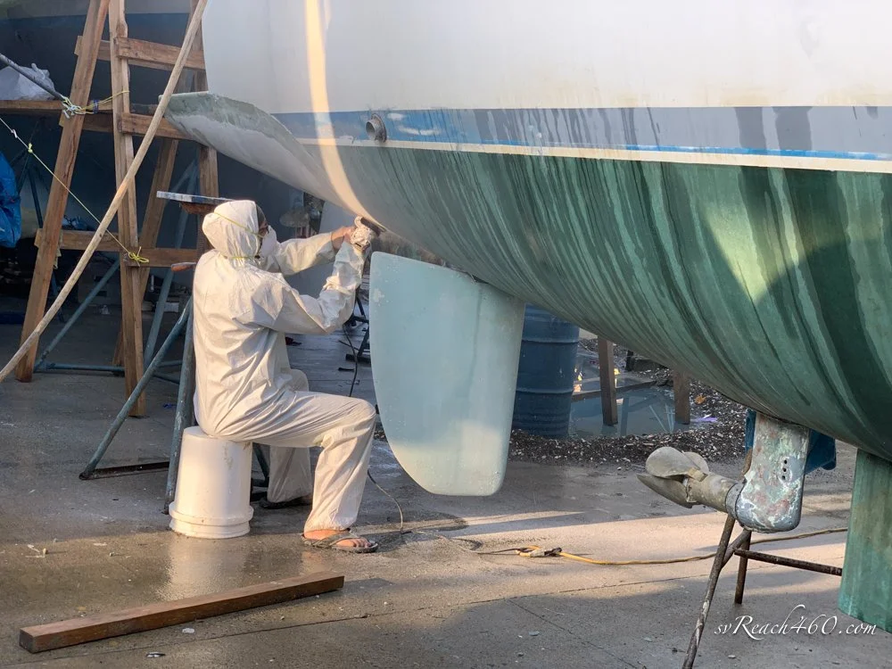
Michele here … what Mark has understandably blocked out is the fiberglass grinding part along the way!
He did a great job getting the stern shape and curved edges pretty perfect.
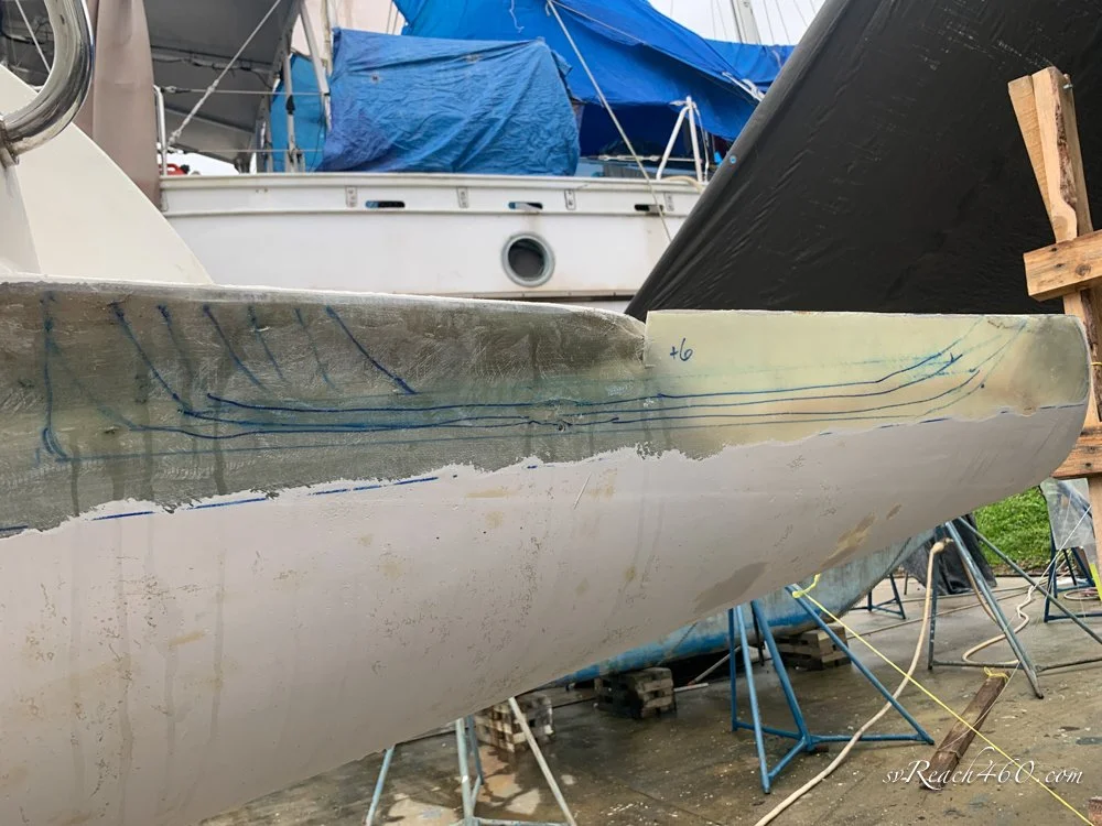

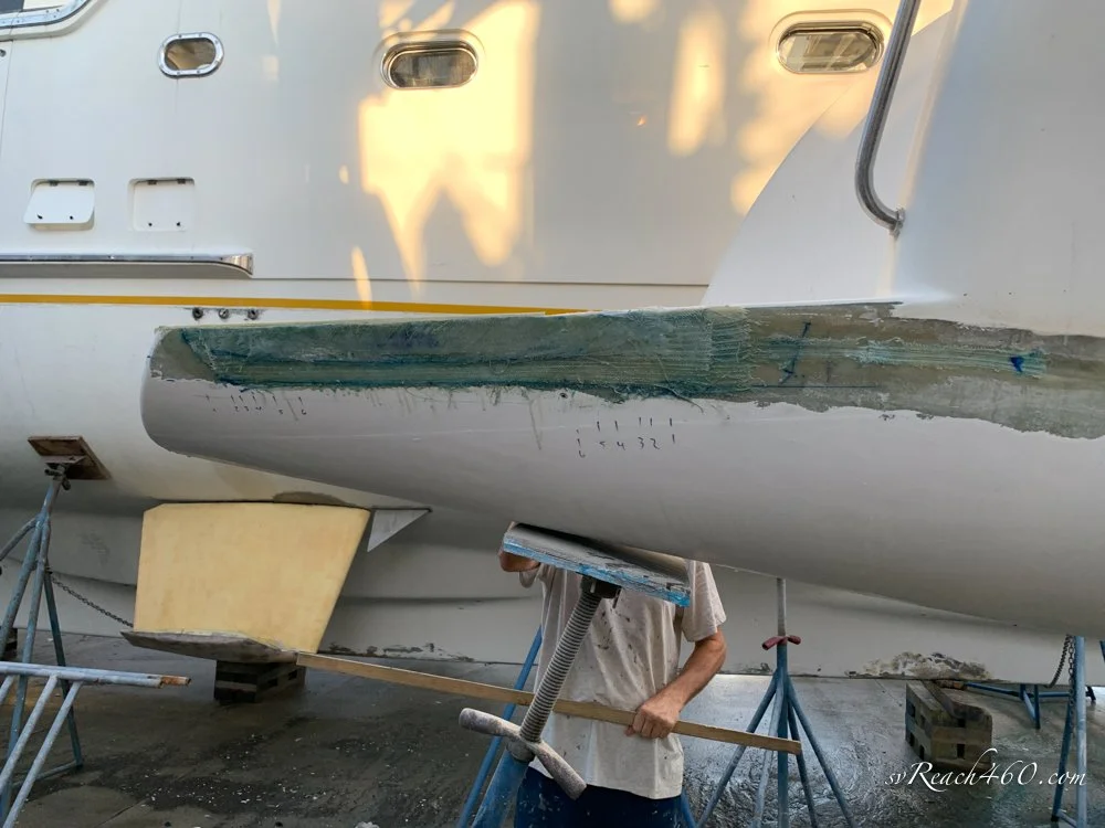

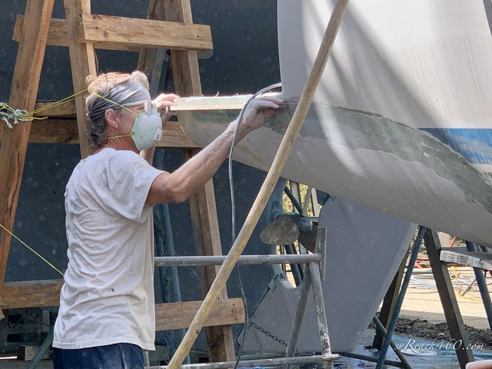




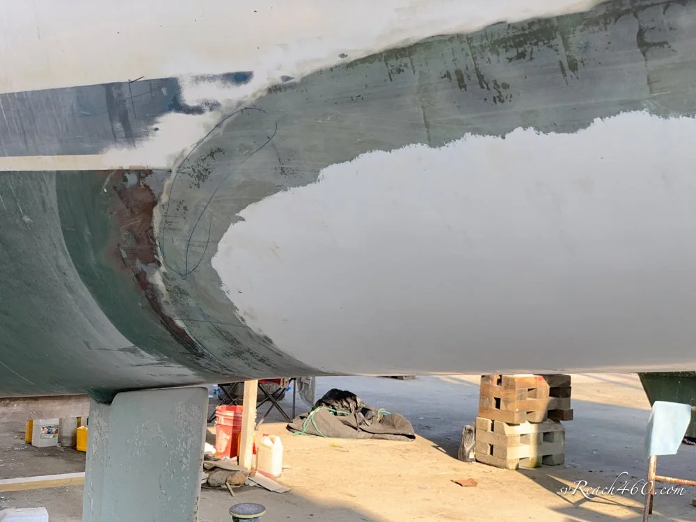


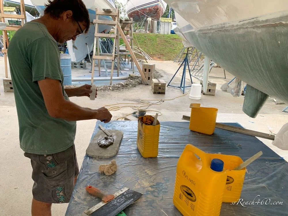


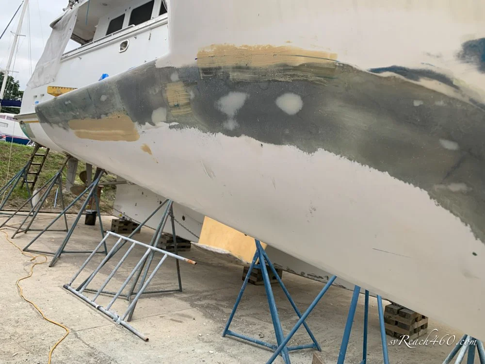


Topsides gelcoat ~ Barrier coat ~ Antifouling:


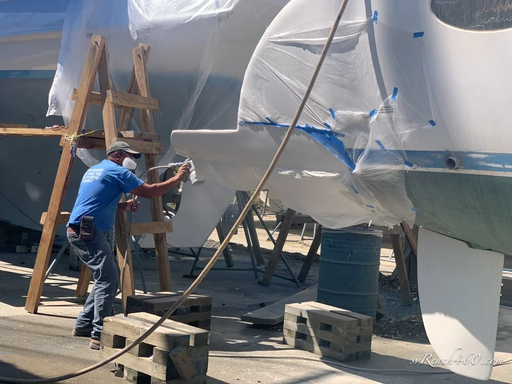
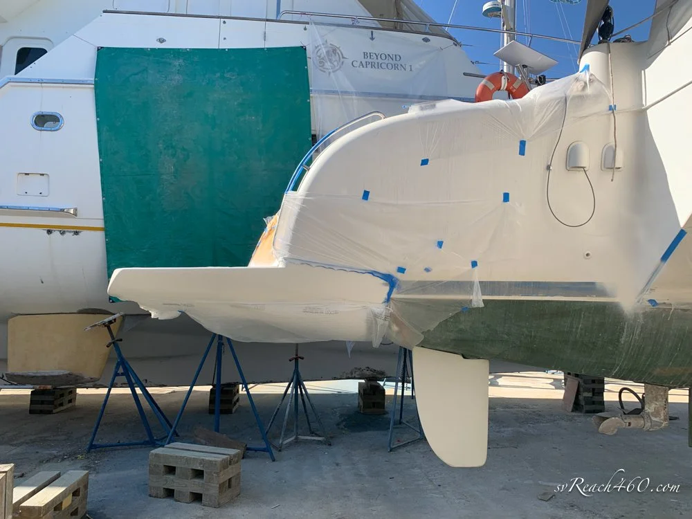
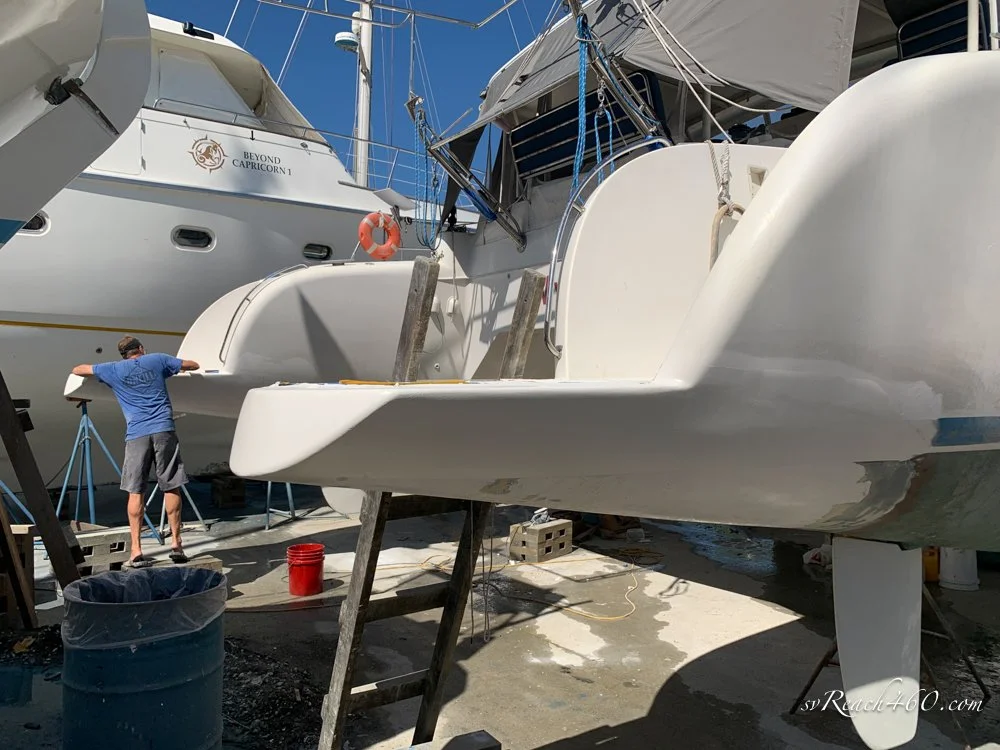

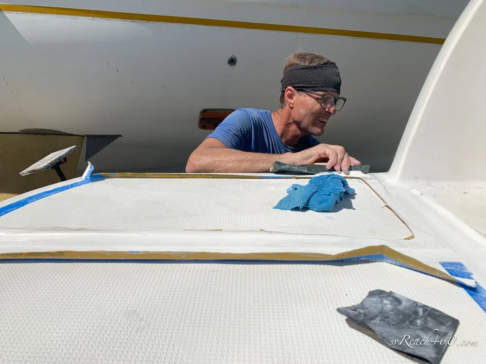


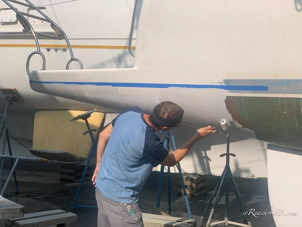
Final product:
Final product


